Image Stabilization Technology
LEARN MATH FOR WHAT? FOR AVOIDING BLURRY VIDEO! Have you ever recorded a video and found that it was shaking so much that you can’t even finish it? If so, it’s likely that your phone doesn’t have good image stabilization technology! The use of image stabilization in filming devices is very important. Without it, all the videos we watch now would make us feel dizzy. Currently, there are mainly two methods of image stabilization: optical image stabilization (OIS) and electronic image stabilization (EIS). In this article, we will focus on electronic image stabilization technology. OIS technology will be discussed in more detail in the next article.
Optical Image Stabilization
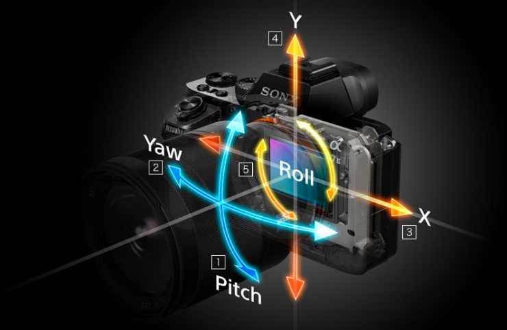
The gyroscope sensor measures and collects data on the tilt angle and the level of movement to synchronize with the camera system. From there, the lens or camera module will move in the same direction as the user’s movement. At this time, the camera system and the frame will be on the same coordinate system.
However, changing the lens based on these parameters requires a minimum distance between the lens and the sensor. Therefore, this sensor is usually found in cameras, but it is impossible to integrate it into a compact smartphone. The mobile phone version is not very effective. Therefore, we need another image stabilization method, which is software image stabilization.
EIS motivation
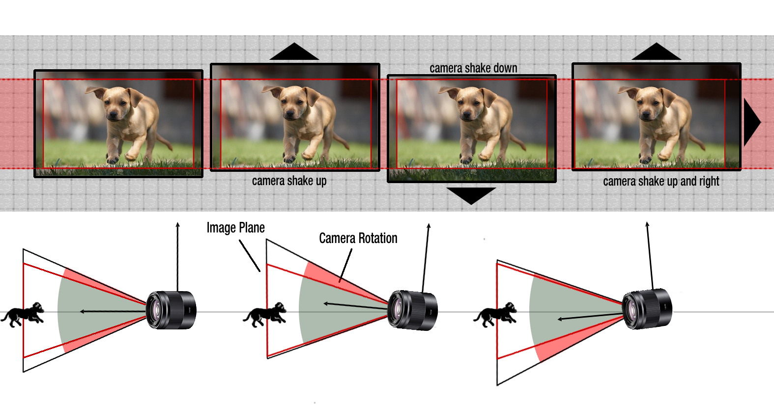
The idea of EIS is to find a way to crop the image of each frame to make the video as smooth as possible, meaning that the offset of the images is minimal. Like this dog video, but we don’t need to rely on the gyro sensor to know if it’s rotating left, right, or up, down, but only on the images collected.
Spherical Projection
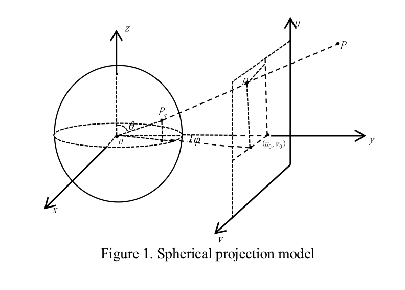
We will assume that two different camera angles can be reached by a rotation and translation operation. We will use the spherical projection method: convert the 2d image to a 3d image on a circle: project the plane onto the circle. We consider point P characterized by phi and theta:
Phi is the angle formed by the projection of OP on Oxy and Oy, while theta is the angle between OP and Oz counterclockwise. Then the projection of P on the circle is the point P’(x, y, z) satisfying:
x = sin theta * cos phi y = sin theta * sin phi z = cos theta
We can easily solve for theta and phi from the coordinates (u, v) of point P on the image plane captured by the camera.
Finding relation between two images
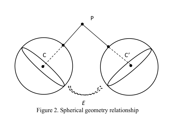
From two different camera angles C and C’ with corresponding parameters, we need to find a quantity that characterizes the rotation angle and translation angle.
The two viewpoints C and C’ are related to each other by the essential matrix E. From the origin point, we can deduce the image x on C, and we need to know the image x’ of it on C’, based on the equation x’T Ex = 0.
And from the matrix E, we can deduce the rotation matrix R and the translation vector t. This will require the RANSAC8 algorithm (useful when the image has many extraneous objects) and the ASIFT point matching method (useful when the image is not changing much, only one object at multiple angles of view)
RANSAC Outlier
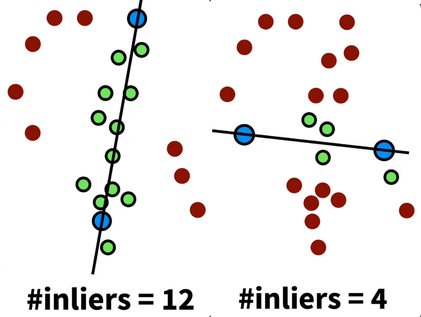
The RANSAC algorithm works basically as follows: First, a number of sample points are selected. Then, two points are selected from them, and a line is drawn connecting them. Then, it is determined how many points are close to the drawn line. The distance between the points and the line is defined as “close” here with the delta parameter: points with a distance to the line < delta are considered close. This is applied to all sets of 2 points and the best set with the most inliers is determined. Then, the points that are not close to the selected line are considered outliers. Lets see how we’ll use this to find the corresponding points.
Applying RANSAC
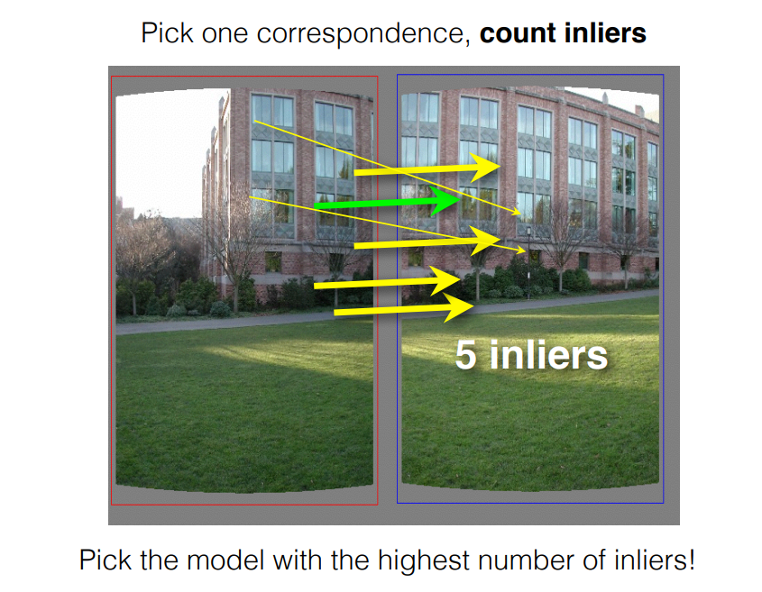
To align two images, we first need to predict the transformation that is used to align them. This transformation is usually a combination of translation and rotation. We will need to add some parameters here.
Once we have predicted the transformation, we can select two points in each image and then use the transformation to warp the remaining points in the second image. The set of points that produces the most inliers will be the set that uses the corresponding transformation.
The limitation of RANSAC is that the time it takes to run increases as the number of outliers and the number of parameters that need to be used increases. It is also not suitable for images with many answers.
Here is a link to a more detailed explanation of RANSAC: https://www.cs.cmu.edu/…/10.3_2D_Alignment__RANSAC.pdf
ASIFT
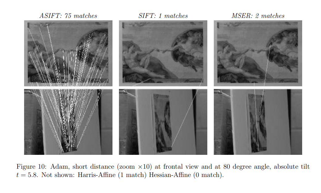
The ASIFT method is also a method for determining corresponding points. ASIFT is based on the principle of affine geometric transformation. In the figure, we can see the strength of ASIFT compared to other methods. We will talk more about it in the following articles.
